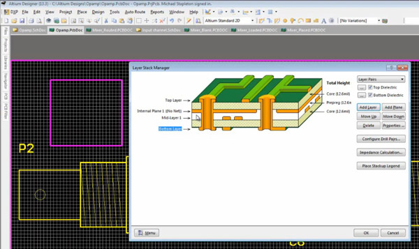

There are a number of panels in Altium Designer, the default is that some are docked on the left side of the application, some are available in pop-out mode on the right side, some are floating, and others are hidden. such as the sheet size and Snap, before you begin drawing your PCB. The main document editing area of Altium Designer, shown on the right side in Figure 1. Altium Designer is irrefutably one of the commonest sophisticated PCB design tools.

The Altium Designer environment consists of two main elements: The DXP platform underlies Altium Designer, supporting each of the editors that you use to create your design. When you select All Programs > Altium Designer from the Windows Start menu to run Altium Designer, you are actually launching DXP.EXE. In addition, the Altium Designer environment can be customized to meet a wide variety of users' requirements. Including a schematic, PCB module, and an auto-router and differential pair routing features, it supports track length tuning and 3D modeling.Īltium Designer includes tools for all circuit design tasks: from schematic and HDL design capture, circuit simulation, signal integrity analysis, PCB design, and FPGA-based embedded system design and development. All design rules are created and managed within the PCB Rules and Constraints Editor dialog. The hole size is the diameter of the hole to be drilled through the pad/via during fabrication.

It is developed and marketed by Altium Limited. This rule specifies the maximum and minimum hole size for pads and vias in the design. Right click on the schematic, Options > Sheet., and uncheck the Title Block box.Altium Designer is one of the most popular of the high end PCB design software packages on the market today. That will help us to have the perfect PCB. We can customize the design rules such as track width, pad sizes, clearance and etc as we needed. If we did any changes on the PCB design layout which are not on the schematic those changes also can be export to the schematic. Open the PCB Rules and Constraints Editor dialog. In altium designer we can easily import the changes we made on the schematic. In your schematic sheet, disable the Title Block to introduce yours. First, we need to configure a basic rule for net-to-net clearance for all nets in our PCB.You can see other default special strings here: Schematic Text Strings. I put some Altium default parameters ( SheetNumber, SheetTotal, CurrentDate and Title) and two that we'll create ( VersionRevision and Project). These special strings will be replaced automatically by Altium when you create a parameters with the same name. I put these strings in red to show that are special strings starting with '=' sign. Use lines and strings to create the fields. In your schematic library, add a new component called Title_Block.You can do that creating a schematic component and introducing the parameters you want. I'll answer but don't worry if someone delete the question.


 0 kommentar(er)
